|
Introduction
This "work-in-progress" aims to
investigate the Rudall & Rose Patent Head, designed and
marketed by that leading 19th century flute company. This head
attempted to deal with the wide range of pitches which might have
been encountered in this time, firstly by providing a very long
tuning slide (extendable by 30mm and therefore by about 30 Hz)
and secondly, by automatically moving the stopper at the same
time as extending the slide, to keep the two in their most
harmonious relationship.
We will attempt to identify the reasons why the
head was thought to be needed, how it worked, how well it worked
and what it can tell us about the flute of the time. While our
investigation proceeds, here are a few images and notes to dwell
upon ...
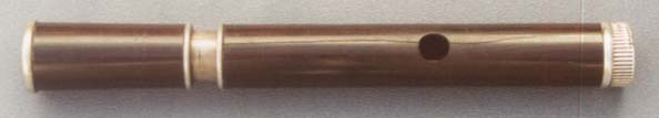
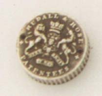
The Rudall & Rose Patent Head under
examination.
See Clinton 1851 Flute to see the head
in conjunction with the flute it was associated.
Note:
The cap, at extreme right, rotation of
which simultaneously extends the tuning slide while
moving the stopper at a different but appropriate rate
The crack through the embouchure, the
inevitable result of shrinkage of a wooden head lined
with unyielding metal
some damage to the cap, probably by
dropping.
The Entrails ...
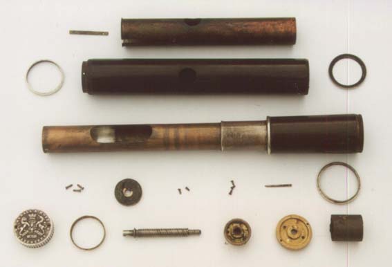
From the top (enumerated from left to right):
Line 1: brass anti-rotation key
(1) and the copper head liner (2)
Line 2: the head (2) with its two end rings
Line 3: the inner
slide, silver sleeve, barrel top ring, and barrel
Line 4: screws to secure flange to top of head (1), flange (2),
screws to secure cap to disc (3), screws to secure boss to top of
inner slide (4), pin to secure disc to shaft (5), ring for lower
end of barrel (6)
Line 5: embossed cap (1), brass ring to strengthen top of head
(where screws secure flange) (2), steel shaft (3), boss (4), disc
(5), stopper (6).
Operation
Rotating the cap (L5-1) rotates the disc (L5-5) attached to it
by screws (L4-3). The disc is pinned (L4-5) to the shaft (L5-3)
which rotates in the flange (L4-2). The flange is secured by
screws (L4-1) which pass through the ring (L5-2), the top of the
head (L2) and the top of the head liner (L1-2).
The shaft has two threaded sections with different rates. The
larger, faster section drives a boss, (L5-4) secured in the top
end of the inner slide (L3-4) by three screws (L4-4). The thinner,
slower end section engages with and drives the stopper (L5-6).
The stopper takes the form of a cylinder of brass with a flange
near its centre. The flange is threaded to take the shaft. A
silver disc is attached at the embouchure end, and the outside of
the cylinder is covered with cork to seal the bore.
As the shaft rotates, it moves the inner slide at a high rate,
and the stopper at a slower rate.
Things to note in the image above:
- the anti-rotation key is normally riveted to the copper
inner slide and locates in a slot just visible in the end
of the copper head liner. In this case, like many others,
the key has been torn off by an attempt to contra-rotate
head and barrel in the normal way. Patent heads can only
be operated by rotating the cap.
- The barrel, barrel top ring, silver sleeve and inner
slide are clearly separate items, but are not easy to disassemble. The far end of the inner slide flares into
the socket region of the barrel and is thus unable to be
removed unless the silver sleeve can be removed or unless
the flared section is bored out. The silver ring was
probably applied next, followed by the silver sleeve - a
firm drive fit on the slide and thus difficult to remove.
There were no compelling reasons to proceed further in
this area.
- The silver plating inside the copper inner slide is in
very good condition where it was protected by the
location of the stopper. Below that it can be seen to be
very tarnished.
- Only partly distinguishable in the image is the
considerable damage to the top of the silver sleeve on
the copper inner slide. This damage was caused by the
anti-rotation key, torn from its normal position on the
slide, and repeatedly forced against the top of the
sleeve by further attempts to separate the slides.
- The inside of the flange at L4-2 is covered by a thick,
gummy substance, possibly a degraded grease intended to
lubricate the shaft which passes through it.
- The disc, flange, boss and stopper have all had any
surplus material removed by turning, presumably in an
attempt to shed unnecessary weight.
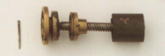
The Engine
To make the operation a little clearer, here is an image of
the inner active parts separately assembled. From left to right:
cap, secured to disc by two screws
pin that secures disc to shaft which
links remaining items
disc, driven by cap
flange in top of head through which disc
passes
boss in top of inner slide and which
drives inner slide
stopper
What actually happens?
The table below shows that the distance from the
centre of the embouchure to the face of the stopper decreases by
5mm as the slide is extended from fully in to its maximum
extension of around 30mm.
| Distance: |
Slide
Extension |
Embouchure
to End |
Stopper
to end |
Embouchure
to Stopper |
| |
0 |
156 |
178 |
22 |
| |
10 |
166 |
186 |
20 |
| |
20 |
176 |
195 |
19 |
| |
30 |
186 |
203 |
17 |
| Total movement: |
30 |
30 |
25 |
-5 |
To see the Rudall & Rose Patent for this device, see:
Rudall & Rose 1832 Patent Head
If you have information to add about the Patent
Head, or questions you'd like us to try to answer, please contact
us.
Back to McGee Flutes home
page...
Created 11 June 2001 |